An industrial heat exchanger specification typically defines the design, performance, materials, operating conditions, and applicable standards for the equipment. Below is a general specification template that can be adapted for most industries.
Industrial Heat Exchanger Specification
1. General Information
- Equipment: Heat Exchanger
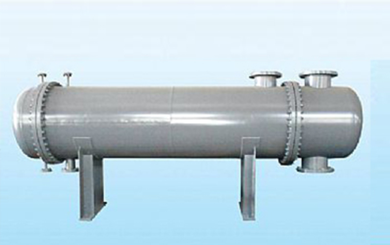
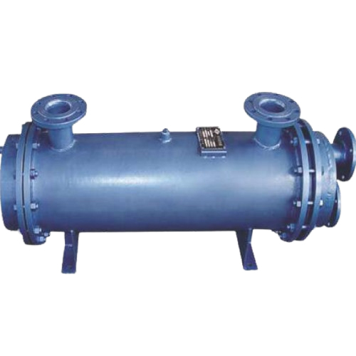
- Type: Shell & Tube / Plate / Air-Cooled / Double Pipe
- Service: Process Fluid Cooling/Heating
- Quantity: 1
- Tag Number: HX-101
2. Design Conditions
| Parameter |
Shell Side |
Tube Side |
| Fluid |
Hot Process Fluid |
Cooling Water |
| Flow Rate |
20,000 kg/h |
25,000 kg/h |
| Inlet Temperature |
150C |
30C |
| Outlet Temperature |
90C |
45C |
| Design Pressure |
16 bar |
10 bar |
| Design Temperature |
200C |
100C |
| Operating Pressure |
12 bar |
6 bar |
3. Thermal Design
- Heat Duty: 1.2 MW
- Overall Heat Transfer Coefficient: As per thermal design
- Log Mean Temperature Difference (LMTD): Calculated
- Fouling Factor:
- Shell side: 0.0002 mK/W
- Tube side: 0.0001 mK/W
4. Mechanical Design
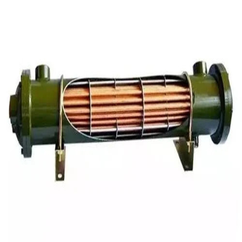
- Exchanger Type: Shell & Tube
- TEMA Type: AES (or as required)
- Shell Diameter: As per design
- Tube Length: 36 m
- Tube Outside Diameter: 19.05 mm (3/4 in)
- Tube Thickness: 1.65 mm
- Number of Tubes: As required
- Tube Pitch: Triangular/Square
- Number of Tube Passes: 2
- Shell Passes: 1
- Baffle Type: Single Segmental
- Baffle Spacing: 2050% of shell diameter
5. Materials of Construction
| Component |
Material |
| Shell |
Carbon Steel ASTM A516 Gr.70 |
| Tubes |
Stainless Steel 316L |
| Tube Sheet |
Carbon Steel with SS Cladding |
| Channel |
Carbon Steel |
| Gaskets |
Spiral Wound SS/Graphite |
| Bolting |
ASTM A193 B7 / A194 2H |
6. Connections
- Shell Inlet/Outlet: Flanged, ANSI Class 150/300
- Tube Inlet/Outlet: Flanged
- Vent Connection
- Drain Connection
- Thermowell Connection
- Pressure Gauge Connection
7. Codes and Standards
- ASME Section VIII Div. 1
- TEMA Standards
- API 660 (for shell-and-tube exchangers in refinery service)
- ASME B16.5 (Flanges)
- ASTM Material Standards
8. Inspection and Testing
- Hydrostatic Test
- Pneumatic Leak Test (if required)
- Non-Destructive Testing (RT, UT, PT, MT as applicable)
- Material Test Certificates
- Positive Material Identification (PMI), if specified
9. Surface Protection
- Internal Coating: As required
- External Painting: Epoxy primer and polyurethane topcoat
- Insulation: Mineral wool or calcium silicate (if required)
10. Documentation
- General Arrangement Drawing
- Mechanical Data Sheet
- Thermal Design Calculation
- Fabrication Drawings
- Welding Procedure Specifications (WPS/PQR)
- Inspection and Test Plan (ITP)
- Material Certificates
- Operation & Maintenance Manual
11. Performance Guarantee
- Heat duty as specified
- Maximum allowable pressure drop
- Leak-free operation
- Design life: Typically 20 years (subject to service conditions)
This template can be tailored for specific applications such as power plants, oil and gas, chemical processing, HVAC, food processing, or pharmaceutical industries by adjusting the design conditions, materials, standards, and performance requirements.
 GST: 33BGTPS0823H1Z7
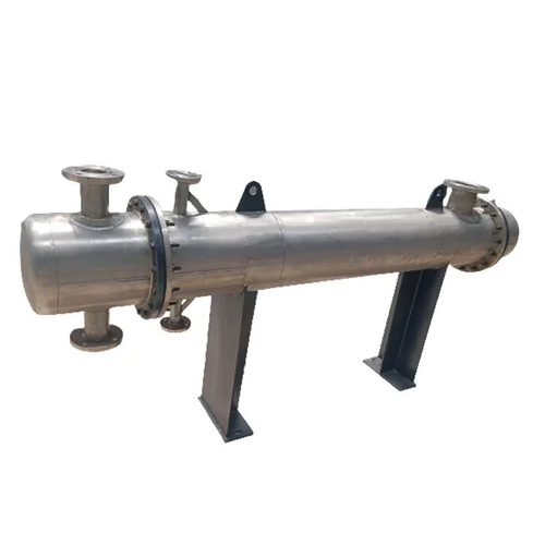


 Send Inquiry
 Send Inquiry